Hey Hoosierdaddy, I've actually did the single fin box idea after some trial and error before I came up with same thought on the exhaust fan on the back of my case, and it works great. Very little restriction, and you would have to be in pitch black darkness to see any light and only after your eyes adjust to the dark. Other wise no light comes out and is 99% effective. But I like your z fin idea also, as well as Scrubninja's design to.

You are using an out of date browser. It may not display this or other websites correctly.
You should upgrade or use an alternative browser.
You should upgrade or use an alternative browser.
DIY: A new angle on light proof vents
- Thread starter ScrubNinja
- Start date
lol, it's kind of experimental. I'm always browsing PC modding stores, and I kept noticing these cold cathode CCFL kits. I made a thread asking about them and noone knew for sure if they could be used, but then I found a guy on another site who did a grow with them years ago.

That guy got .2gpw (time is not figured into this figure, just straight grams:watts) and clearly wasn't even trying. Then I found 420.se on here was using one ripped out of a scanner over his cuttings. And now here I am with this crazy ass vortex space machine whatever it is. Just waiting on a few parts and it'll steam into action. A couple of other people have decided to give them a try too. You can check out the whacky adventures over here if you'd like")
Sadly, since it's a tubular cab, I couldn't use my light trap design! Gutted!
That guy got .2gpw (time is not figured into this figure, just straight grams:watts) and clearly wasn't even trying. Then I found 420.se on here was using one ripped out of a scanner over his cuttings. And now here I am with this crazy ass vortex space machine whatever it is. Just waiting on a few parts and it'll steam into action. A couple of other people have decided to give them a try too. You can check out the whacky adventures over here if you'd like
Sadly, since it's a tubular cab, I couldn't use my light trap design! Gutted!
M
mrred
tag,, good ideal
barth
Active member
I was wondering how large id need to make an intake like this to properly vent a cab that is 33" by 26" by 60"? I am using a GrowBright 6" fan rated at 424 cubic feet per minute. I have it on a speed controller set on low.
I also have a 4" hole that connects a second veg room to my flower room. The scrubber sucks air from my flower cab and this sucks from the 4inch out of the veg cab the veg cab is 18" by 30"
I have a space of about 15" by 5 inches to work with.
I also have a 4" hole that connects a second veg room to my flower room. The scrubber sucks air from my flower cab and this sucks from the 4inch out of the veg cab the veg cab is 18" by 30"
I have a space of about 15" by 5 inches to work with.
Cheers all!
Cheers all!
Hi Barth. For your grill, once you have ensured the flow is unblocked beforehand (second cab? 4" hole? huh? I will just assume you know what you're doing in that dept. Hoosier's airflow thread is the place to learn), your 6" exhaust equals 28.3 sq inches. So to follow the dummies guide to intakes (2x) you will need your intake area to be 56.6 square inches of free flow.
We need 56.6, plus the grill will be blocking roughly one third, so we want 56.6 + half of 56.6, which is 84.9 sq in. You need 84.9 sq in of my grill to have 2x intake. Type this number into a calculator and hit "sqrt" and it gives us 9.2. Your grill, using the same fin thickness, and spacer thickness as mine, needs to be at least 9.2" x 9.2".
Let's look at your 5" restriction which is now causing you problems. We take the 84.9 (total grill size needed) and divide by the restricting dimension. So 84.9 divided by 5" and it equals 16.98 so lets call it 17. Your grill can also be sized 17" x 5".
I always go as large as I can with intakes as long as it doesn't drop negative pressure enough to allow smell to leak out.
That sounds really cool SHO! Pics would be fantastic, and best of luck.
Igotyourback
Member
Such A Great Idea
raphaelwilliams
New member
That is a really cool idea. How does it work? I bet that aluminum angle iron was expensive though?
Raphael, I never actually used it for a grow, haha. I built the cab shown in the first post then stopped work on it, and the new cab I made is tubular so it isn't suited for this grill. I wanted to make one for my pll cupboard but I was just too lazy.
The aluminium is quite cheap in lengths. Cheap enough to make it worth it, over buying a pre-made grill, but then again, I'm in a remote country so maybe that effects the price of pre-made grills. I've never tried pre-made but from all accounts they're quite (more?) restrictive. The main thing that I don't like apart from the cost and restrictiveness is that they don't seem to give any figures as to how much blockage their grill causes. I mean, it's a piece of ventilation equipment...how can they not mention any figures? How is anyone to realistically calculate their system? I wouldn't buy a fan or carbon filter without knowing the size at least. Does anyone using a pre-made grill have any figures provided by the manufacturers concerning how much it blocks the flow? Not trying to sell my idea over a pre-made, but these are my concerns with them.
Barth, I was thinking you could use more angle to frame around the grill and make it look pretty, and let you mount it easier.
Thanks Igotyourback
...Would anyone who owns a commercial light trap using this principle care to give the dimensions and gaps/thicknesses it uses?
Great idea! Simple, cheap, effective! Truly DIY worthy! Thanks SN!
Here is a small contribution to the cause.
Frame (O.D.) 9-7/8” X 9-7/8”
Frame (I.D.) 6-7/8” X 6-7/8”
Frame (depth) 7/16”
Panel (O.D.) 7-7/8” X 7-7/8”
Panel (I.D.) 7-1/8” X 7-1/8”
Panel (frame depth, excluding slot tab) 3/8”
Panel (slot tab) 1/8” x 1/8” x 6-15/16”
Slat (base) 3/4”
Slat (wing at about a 45-degree angle from the slat base) 7/16”
Slat (total width) 1-3/8”
Slat (depth) 5/16”
Slat (spacing) 3/8”
I used an old beat-up tape measure, so I may be off by a sixteenth in one place or another, but it is more or less accurate.
Each unit is comprised of a mounting frame attached to a stack of four panels of just two configurations. A panel consisting of four "slats" with 3/8" space between slats and the sides of the panel frame and a panel of three full slats and two half slats molded into the sides of the panel frame. Each panel's tab fits into the slot on the base of each panel allowing the slats of one panel to span the openings of the other, so sequencing is important for re-assembly.
(*Note the dust pattern on the slats. The molding process seems to leave a bit of ooze on the edges of the slat "wings" creating turbulence/resistance. A file will make short work of it, but I would think a manufacturer would take more pride in Q/C.)
Namaste, mess
Thanks so much, messn!  That's interesting. It looks to have over half the space blocked. Like, approx 2/3rd blockage if I understand right.
That's interesting. It looks to have over half the space blocked. Like, approx 2/3rd blockage if I understand right.Dr. Conjuror
Member
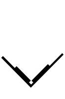
Great job, ScrubNinja. It is not like I don't already have a million DIY projects swimming in my head. But it is a really good idea. I know you said you had "fins" that were 1.55mm thick, but I do not recall if you gave the dimensions of the "V" shape. What is the width of the top of the "V".
Using the description messn'n'gommin' was so kind to give and the fact Hoosier reminded us of ("restricted by the smallest passage"), it seems a lot of the restriction of the pre-made one is the four panels do not seem to be sandwiched veer far apart.
Forgot to mention that it took me reading half the thread before noticing your avatar, That is just perfect (OK I thought I had the will power to resist, but I cannot -- purrrfect).
messn'n'gommin' - how far apart are the panels from one another?
Dr. Conjuror
messn'n'gommin' - how far apart are the panels from one another?
Dr. Conjuror
As best as I can tell, about 3/8 of an inch.
.375" (the space between the slats and the panels) X 6.875" (the opening of the frame) X 4 (spaces between slats) = 10.3125 square inches.
I am currently using a 6" exhaust system and have three of these louvers installed. I was really surprised at just how little (relatively speaking) air flow these things have and have decided to increase flow capacity. With that in mind, I have been working on a design more along the lines of the darkroom louvers, yet try to keep the cost of materials to a competitive DIY edge.
So far, I have twelve 1/16" X 1" X 7-7/8" (allowing for the saw kerf) pieces cut from one of two 8' blanks (about $12 ea.) and using a 10' piece of cornerbead (about $1.50 ea.) for a frame. Since I am a functional computer illiterate and don't know how to post my hand-drawn design on here, but try to picture six of them balanced on their angle and spaced 3/8" apart. With the other six inverted, offset, and spaced 3/8" from each other and from the bottom six, it should give me a panel about 11" X 8". 3/8" (space between angles) X 7" (taking into account frame overlap) X six (the number of openings) = 15.75 sq. in.
I quickly decided that two panels would be worth the cost of an extra 8' blank and as long as it has 50% increase in total area, I feel it only right to increase the cost of the materials by a minimum of 25%. So far, the only thing holding me up is an economical way to keep the whole thing seperated by 3/8". I am considering a couple of options:
1) 1-1/2" shelf brackets (twelve X $.50 to $.75 ea) to hold the bottom ones in place and a smaller one on the offset sides of each row of angles. Follow that with something flexible enough to layer between the two rows of angles and still keep the two rows 3/8" apart.
2) The other option is using the shelf brackets and pop rivets with a spacer to keep the whole thing separated. But, I think that would require a small drill press as the holes for the rivets would demand higher precision.
I could use some help with trying to figure out something cheap and effective to use for spacers. But, I will build this, and possibly another, and report back in a day or three.
I love puzzles!

Namaste, mess
Dr. Conjuror
Member
messn'n'gommin' - Well that space between layers certainly explains the huge static pressure of the pre-made ones.
As far as spacers, I was thinking about using washers. Pardon my doodles...
Profile View....
Bird's eye view....
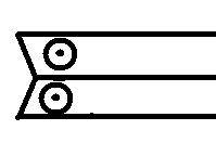
I figured one could set the fin between two things thaat would hold it in the "V" position and then glue the washers to the fin (4 per fin) and once that's is dry, fins could be stacked as normal.
What do you think about it? Seems like a cheap solution ( at least per washer) and there are many sizes of washers that would give you lots of spacing choices (distance between fins.)
Dr. Conjuror
As far as spacers, I was thinking about using washers. Pardon my doodles...
Profile View....
Bird's eye view....
I figured one could set the fin between two things thaat would hold it in the "V" position and then glue the washers to the fin (4 per fin) and once that's is dry, fins could be stacked as normal.
What do you think about it? Seems like a cheap solution ( at least per washer) and there are many sizes of washers that would give you lots of spacing choices (distance between fins.)
Dr. Conjuror
Great work people. Dr C, that should work with the washers. A little fiddly perhaps but it's not like the original method is unfiddly, heheh. Not sure what you mean about measuring the top of the V. It's like /\ so the top is a point. But happy to measure if you clarify. Good luck to both of ya.

