What's new

Help my connect the wires here...

kbobotoor

New member
Okay guys, I'm trying to figure out the lighting for my medcab and realized wiring one myself will allow me for most effective and efficient lighting/placement.

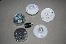
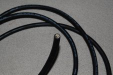
So basically, I have all the parts (with help) and now I just need to know: How do I put this together?

Here's some pictures to clarify the situation, if anyone needs any more info in order to help, I'll be happy to provide!
 

Attachments

  • lighting_1.jpg
    lighting_1.jpg
    74.9 KB · Views: 6
  • lighting_2.jpg
    lighting_2.jpg
    53.9 KB · Views: 6

kbobotoor

New member
There's actually three. And they're just the backs to the white fixtures so you can attach them to the wall and house the wires.
 

eddie.saw

Member
there should be three wires inside there, a white(neutral) black(hot) and a green(ground). put the black on the sliver screws and the white to the silver. the green is your groud and should be screwed into the back of your box. for the plug im not sure but it should tell you which is which. i know the cirular one is ground.
 

FreezerBoy

Was blind but now IC Puckbunny in Training
Veteran
for the plug im not sure but it should tell you which is which. i know the cirular one is ground.

The SMALL flat prong is Hot/Live/Power In. The LARGE flat prong is Neutral/Com/Power Out. You want the escape hatch larger than the entry.


kbobotoor

New member
Anyone willing to give me a visual explanation? I'm confused about such things as, the wiring from socket to socket. Do the wires coming in connect to the same screws as the ones going out, or so I use different screws (in case you notice on the white fixtures, there's two gold and two silver screws).

Edit: FreezerBoy, that diagram helps! I am clearly looking to wire in series. However, when the wire is connected to and reaches the last light, don't the circuit just end and continue through there? In that diagram the wire seems to be entering and exiting from two unknown sources. Shouldn't there be only one wire entering (from the power source)?
 

FreezerBoy

Was blind but now IC Puckbunny in Training
Veteran
I am clearly looking to wire in series.)?

Oh, the humanity! No Series for you. You want Parallel. Electricity works in a circle or circuit. If the current fails to make a complete loop from the power company, through your home, and back to the power company, nothing works. In Series, one lamps failure breaks the entire circle and everything fails. In Parallel, one lamps failure has no effect on the circle so everything (other than the failed lamp) continues to work.

The connection method used in Parallel is called a "pigtail". Your in line connects to a wire nut with 2 other wires (3 total) one of which is connected to your lead, the other to another pigtail. Lather, rinse, repeat until the circuit is finished.

Do yourself a favor and Google "pigtail wiring" for visual examples. Better yet, go to Home Depot and get an NEC approved wiring book. For less than the cost of a single pizza, you can keep yourself, your garden, and your neighbors safe from harm.


CloudNine

Member
You can connect them to the same screws or the another screw of the same color since they are both connected via that small metal thing.

You want to wire your lights like this:

Light1.......... Light2........ Light3
..../+-----------+-----------+
....\_-----------_-----------_

+=postive terminal (Gold color screws)
_=Negative terminal (Metal color screws)
.=cord from the wall (Ignore light green . since they are spacers to line up my diagram evenly)
\ /= Wires from cord attaching to light1 terminals.

Light1 is of course connected to the cord, and lights 2 and 3 are connected to light1 terminals via extra wire. Solid wire 14 gauge or lower.(Bigger wire)

The positive wire from your cord (White) will attach to the gold screws.

The ground and neutral (Black and Green) will attach to the other screws. One wire on each screw will work fine.

From there you just wire the terminals from light1 to light2 and from light2 to light3.

Hope that helps.
 

kbobotoor

New member
You can connect them to the same screws or the another screw of the same color since they are both connected via that small metal thing.

You want to wire your lights like this:

Light1.......... Light2........ Light3
..../+-----------+-----------+
....\_-----------_-----------_

+=postive terminal (Gold color screws)
_=Negative terminal (Metal color screws)
.=cord from the wall (Ignore light green . since they are spacers to line up my diagram evenly)
\ /= Wires from cord attaching to light1 terminals.

Light1 is of course connected to the cord, and lights 2 and 3 are connected to light1 terminals via extra wire. Solid wire 14 gauge or lower.(Bigger wire)

The positive wire from your cord (White) will attach to the gold screws.

The ground and neutral (Black and Green) will attach to the other screws. One wire on each screw will work fine.

From there you just wire the terminals from light1 to light2 and from light2 to light3.

Hope that helps.
Thanks so much, that's exactly the information I needed to know. Now all I need is an effective manner in which to cut this really thick cable, in order to get to the smaller cables. I'm sure Home depot will have an answer for me.

Thanks everyone!
 

FreezerBoy

Was blind but now IC Puckbunny in Training
Veteran
The positive wire from your cord (White) will attach to the gold screws.

The ground and neutral (Black and Green) will attach to the other screws. One wire on each screw will work fine.

Wire colors can change from nation to nation. We need some clarification. In the States, the above quote is backwards. In the States, Black is power (ungrounded) White is Neutral (grounded) and Green is not part of the circuit. Green grounds the metal enclosures the wiring is in.

According to the NEC "Ungrounded wires are known as "live" or "hot" or "energised", which means they have a voltage."

"The grounded wire is white in color ... is never fused ...never switched ... never (to) be used except as a grounded wire."
 

CloudNine

Member
I live in the states. I work with electronics almost on a daily basis. The only time I've seen a black power wire is when it has white lines on it to indicate it's hot, and not ground, which are usually black.

Usually being the key word.
 

FreezerBoy

Was blind but now IC Puckbunny in Training
Veteran
In the following diagram, the thick line is Black (hot/live/power in) the thin line is White (neutral/com/power out)


This is based on the NEC or National Electrical Code; The governing body for all electrical wiring in the US.
 

isit4.20yet

Member
In electronics, frequently the circuit will have a negative ground so you end up with the black wire being ground in many cases. In AC wiring, the electrical codes state that the white wire is ground. I'm mostly an electronics tech, but i've done some residential wiring too.

If you want to save a lot of trouble and time, go to Home Depot and pick up one of those 3 or 4 lamp vanity lamp strips. They go for around $12-15. You hook up 3 wires and screw them down. Install CFLs. Done.
 

kbobotoor

New member
I know for a fact that Green is the ground. I'm sure it's not hard to find out which the white/black is. I'm not going to give up now because we can't agree on colors, haha.
 

Jellyfish

Invertebrata Inebriata
Veteran
winner@420giveaway
Can you wire fluorescent tube lights together in parallel, the same way you wire CFL lights together? Thank you. Mahalo
 
Top