What's new
  • Happy Birthday ICMag! Been 20 years since Gypsy Nirvana created the forum! We are celebrating with a 4/20 Giveaway and by launching a new Patreon tier called "420club". You can read more here.
  • Important notice: ICMag's T.O.U. has been updated. Please review it here. For your convenience, it is also available in the main forum menu, under 'Quick Links"!

relays,contactors, PLC's etc

Y

yamaha_1fan

Lets talk about all these cool devices and how they can help design things in our grow rooms.

I have a couple questions

Whats a SP/DP and ST/DT relay? I figure SP/DP indicates whether it is switching both poles like a hot and neutral or two hots versus just one hot? And single throw means it is turning the device off and on? And a double throw means it is switching the power from one device to another like in a flip flop?

Is a contactor just a big relay?

I see some people using PLC's. What advantage do they have over a simple timer?

I plan on setting up a larger lighting set up soon and want to see what kind of bells and whistles I have to play with.
 

Stay Puft

Member
I will try to answer. (Or point you to the answers)
1) Relay contact arrangement: You are correct. The different types are typically used in the manner you expressed. (edit -i misread the question-sorry)


2)A "Contactor" is a type of relay that is typically intended for high power. (As opposed to a "signal" relay.)
Yes a contactor is a big relay!

3)Why I use a PLC versus a plain old timer? In two words "Features" and "flexibility".
More expanded version:
In my case:
I started with a plain old timer, but then I wanted to add a delay-on relay to prevent hot starting the bulb during a temporary power outage. Then I decided I also wanted to add a thermal switch to remove power if the temperature got too hot. I then wanted to connect this to my phone dialer so it could alert me of conditions that required immediate attention.

In the end I had an orgy of mechanical relays, plus the Timer. I had spent a small fortune in Relays. (delay-on etc.) Performing all the tasks with a PLC was trivial and very, very easy to change if you need.
Another example: Want to make the outputs flip-flop? This should take minutes to program and should not involve a screwdriver/rewiring at all!(that is flexibility)

When I looked at the cost and flexibility of a nano-PLC, it made sense too me!
BTW- I did not want a PC based system at the time. (I have been tinkering with that too).
Well that all i know... I hope others chime in as well.
Good Luck!
Stay_Puft
 
Last edited:
A

Azeotrope

I am using a PLC at the moment. It is a slightly out of date CPC "BCU" (building control unit). It is networked with a CPC 8input/8output board. I am monitoring 3 temps in the cabinet (freezer). Using these temp inputs to cycle fans at extreemly low cabinet temps and in the future to monitor CO2 and more...... The relays (outputs) are simply pilot duty. I generally cycle a DPDT 10A relay (icecube style) that in turn cycles the lights and or fans. They could be set-up to pulse a solenoid for CO2 if wanted down the road.

The 56 available schedules give me the chance to finally do sunrise and sunset lighting. I am able to turn on a little 150w hps at 7pm and the 400w CMH at 8pm then cycle of the 150w at 8:30. At hour #10 I bring the 150w HPS on and drop it at the end of twelve. The CMH cycles off at the 11th hour.

This unit can be set to calculate/monitor dam near anything and can record data for 3days or more at 3 minute intervals. Now granted, I have access to some surrendered (due to remodel) 1995 - 2002 building control equipment, but anything that gives greater monitoring and custom options is a big step up from the basic timer I used to use. I will post some pics of the gear later.

BTW - I don't know if all that funny light schedules will do anything at all, but it is cool to play!!!!!
 
Last edited:
Y

yamaha_1fan

Do the PLC's require a PHD to program? I read alittle about them on Wiki and they seemed like they may be for advanced users?
 

hoosierdaddy

Active member
ICMag Donor
Veteran
They require ladder logic knowledge.
Simply another form of code. Not hard to get the basics.
 

Stay Puft

Member
You were probably reading on wiki about the older type PLCs intended for industrial use. This newer class of "nano-PLCs" usually come with software to aid in programming them.(sometime the software cost $) These are intended for a more "consumer" based crowd. That aside, If you just want to "plug-N-grow" there are probably off the shelf solutions available for you. But OTS usually means you will have to operate within the constraints of that systems design. (ever change your mind.. I do!) I myself did not find programming one of these too difficult.(self declared idiot :nono:) But it DOES take some time/effort.

I have a older Omron Zen "nano-PLC". The programming application is more like old fashion ladder logic just like hoosierdaddy mentioned. You can download the demo software for free and play with it.
http://www.zen.omron.co.jp/eng/index.html
I am not saying buy this.. just play with the program/simulator to see if it makes sense to your geek side.:muahaha:
I am not attached to the Omron Zen model. It works and I found a couple of them used/cheap.) The one the other guys are using is fine too.
If you are interested in these, I would suggest reading the manual and trying out any demo software (if avail) before purchasing anything.

BTW-You typically download the program to the nano-PLC via a cable. (BTW-Some companies rip you off ($) for the cable.) Some can be programmed via the front panel buttons if you enjoy pushing buttons all the live-long day. ;)
Regards,
Stay_Puft
 
Last edited:
Y

yamaha_1fan

hoosierdaddy said:
sp=single pole
st=single throw
dp=double pole
dt=double throw

Wheres the little hammer guy? I already knew that silly, I stated that in my post more or less. What I wanted to know was what was the difference, especially between ST and DT but I think I got that clarified.

Stay Puft, yes I believe they were talking more about industrial PLC's in the auto industry etc.


The reason I am thinking PLC, is I love toys first of all and I am recovering control freak :d So the PLC seems cool.

Secondly and more importantly, I feel very confident I have a larger grow in the near future. Goal is 20-30# per month and we will be flipping 15-20K of lights. These PLC's seem like they would be great for delaying the switch to 3-4k at a time.

I have an immediate need for a relay or contactor. Seems like my inline A/C thermostat is on the frits. Regardless of temp, the A/C wont shut off. I have a sentinel CHHC that I bought. I dont physically have it in my hands but its on it way.

The controller has a 120 output for the A/C. My A/C is 240. I looked on grainger and they have like 200 contactors and they seemed real expensive. Not sure if I was looking at the right ones, $250 for a 20 amp contactor?

Can someone tell me which one I need to make this work? I was told I could also switch my 120V fans off the same contactor by just switching the hot, and leaving the neutral connected. My BIL was supposed to get one for me but not sure how thats going to work out.
 
Y

yamaha_1fan

http://www.foxelectricsupply.com/co....asp?qsCatID=25683&qsProductNo=GEDCR453AB3AAA

Definite Purpose Contactor,25 Amp 3 Pole 120 Volt Coil

I am thinking that would work? I know the coil is what switches it and that is controlled by the timer or in my case my CHHC. What it doesnt say is what the output is rated at/ My BIL said they are usually all rated up to 250 V, then they have ones from 250-600?

d_5900.jpg


Can you explain how that gets wired up?
 
B

badugi

As stated, you have a 3-pole contactor pictured... for a typical 240v lighting application, you need only a 2-pole, NO (normally open), 120v coil preferred. Pretty simple, hook up one side to line, other side to load, coil to 120v timer.

These contactors should be typically rated to 600v. Just make sure you get one with the right coil voltage, and correct amperage rating for the correct type of load (inductive, restrictive, or both).

You don't need fancy, expensive (extremely expensive when you're talking about switching these types of loads) PLC's to delay banks of ballasts flipping on. Look for time-delay devices or relays/contactors. Or use a separate timer for each contactor. The only real practical advantage in our field is that it will help empty your wallet faster.

Here's mine using a pair of 30A contactors. It's using two separate 30A sources due to my specific setup configuration.


(Those are old labels on the box cover, need to scrape 'em off; pictured inside box is 95% wired, missing some heat shrink tubing & wire nuts.)

Got 7 NEMA6-15R 250v receptacles and a digital timer all integrated into the 8x8x6 Hubbell Wiegmann NEMA junction box. Took a long-ass time drilling out the holes on the second version (first version used receptacle boxes attached to offset nipples).
 
Last edited:

hoosierdaddy

Active member
ICMag Donor
Veteran
Sorry, yam..yeah I need the hammer. What could I have possibly been thinking to tried to clarify something. Especially when you have such a good handle on this.

badugi, the real beauty of a controller (such as the AB PICo and other families) is the remote capability. One can easily monitor and control their grow remotely with a cheap set-up. That won't be done with relay logic.

On the slim chance that someone else might be reading this thread and could possibly have some confusion as to what we are talking about....

 
Last edited:

Stay Puft

Member
I must confess that I initially replied with a switch description too. (I edited it out.:spank: 
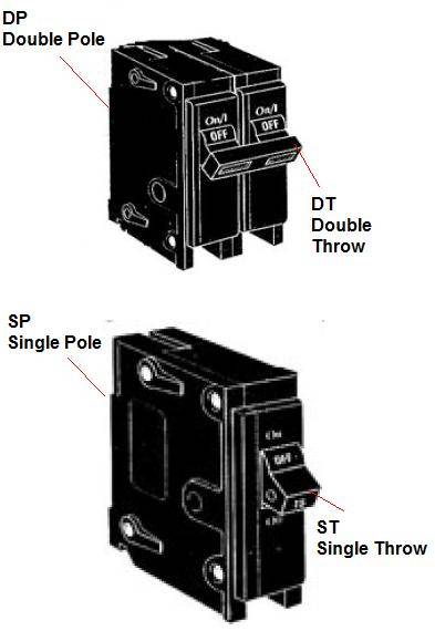
) We did that because you asked about the different output switching configurations available on relays.(DP/ST) As you know, a relay is basically a switch controlled by an electrical signal rather than your finger. The definitions of switch configurations applies to relay configurations the same. (DPDT/SPST etc.)

Here is my 2 pennies worth on selecting a contactor/relay.
You must do the following first:
1-Define/Select the desired voltage and current rating for the control Coil.
2-Define the load voltage and current requirements for the relay. Please note that relays have different current ratings for different voltages and types of loads.(Inductive/ Resistive)
You will need to determine the total load your relay will be switching. To help calculate this, devices like your AC should have a plate on it's side stating its power consumption.(Watts,HP or Current.. you do the math.) You will need to add up everything your relay is switching and ensure that is below the max rating of your relay. (IMHO: de-rate relays rating by ~20%)
3-Define/Select the desired switching configuration for the relay. (SPST, DPDT)
Sometimes you cannot find exactly what you want at a reasonable price. In that case , you can consider using multiple relays and your knowledge of their switching configurations to get what you want, at the price you want.


I think Grainger is generally way overpriced on almost everything.
Some places to look:
Digikey.com
Mouser.com
allelectronics.com (off goods- but great prices)
alliedelec.com (prices are high)
You can also get very good deals on relays on flea-bay.
I hope others can suggest some suppliers as well.

IMO- Never buy a used mechanical relay.(Used Solid State relays are ok)
Good Luck and
Happy Tripdaphan induced Nap Day to all!
Stay_Puft
 
Last edited:

Harry Gypsna

Dirty hippy Bastard
Veteran
SP is single pole(or suppressive person[[any1 who laughs at or disagrees with sci-fi-entology is an SP]] if ur a scientologist lol)
DP is double pole(unless ur a porn star-oooouch is all i can say)
DT is double throw.
SP/DT would be single pole double throw.
I dont know what the fuck that all means but i know what the acronyms are
 

Stay Puft

Member
The picture of the CR453 Yam showed has the coil contacts on the side. You cannot see them in the picture. The 3 Main output contacts (L1-L3,T1-T3) will close when you apply the appropriate control voltage across the Coil terminals on the side.
Power applied to Coil=
L1 Connected to T1
L2 Connected to T2
L3 Connected to T3

Power removed from coil:
L1 to T1 (Open)
L2 to T2 (Open)
L3 to T3 (Open)

Here is the datasheet:
CR453 DATAsheet
Badugi has a good example of the wiring in his picture.

HairyG: :laughing:
go read this:
http://www.kpsec.freeuk.com/components/switch.htm
Regards.
Puft
 
Last edited:
Y

yamaha_1fan

So L1 and T2 are seperate and have no conductivity to L2,T2,L3and T3?

If I wanted to switch my 240 A/C I would just run one hot to L1 and one hot to L2? Then connect the A/C hots to T1 and T2?

Now if I wanted to switch my fans as well, could I just use L3and T3 to switch the hot on my fans?
 

Stay Puft

Member
yamaha_1fan said:
So L1 and T2 are seperate and have no conductivity to L2,T2,L3and T3?

If you meant to say "So L1 and T1 are seperate and have no conductivity to L2,T2,L3 and T3?"
Then the answer is YES. Each contact set (T1-L1,T2-L2,T3-L3) is electrically isolated from one another.


You could connect the AC as you said.

For the fan, the way you suggested would work. It is a lil goofy IMO and I would consider using a separate relay instead. (I do not know what you are using fan for) Maybe one of the electrician type people here chime in on this?

Side note:I prefer to switch both Line and Neutral in my 120V applications if I can. I do this because of the extra safety it affords. (ex:What happens if the electrician mistakenly flipped Line/Neutral in the wall outlet plate?) Yes... I am paranoid!

You could use a less expensive relay for the fan as I am guessing the load of the fan is far less than the AC.

I think it would better to have the ability to turn the fan on/off independent of the AC anyway. In example: Staggering the "Turn on" time of the fan and AC would reduce the In-Rush current on your power distribution system.(like circuit breakers) This will also be ready for easy hook-up and control from the new PLC setup your are working on. :muahaha:
Regards,
Puft
 
Last edited:
Y

yamaha_1fan

Stay Puft said:
If you meant to say "So L1 and T1 are seperate and have no conductivity to L2,T2,L3 and T3?"
Then the answer is YES. Each contact set (T1-L1,T2-L2,T3-L3) is electrically isolated from one another.


You could connect the AC as you said.

For the fan, the way you suggested would work. It is a lil goofy IMO and I would consider using a separate relay instead. (I do not know what you are using fan for) Maybe one of the electrician type people here chime in on this?

Side note:I prefer to switch both Line and Neutral in my 120V applications if I can. I do this because of the extra safety it affords. (ex:What happens if the electrician mistakenly flipped Line/Neutral in the wall outlet plate?) Yes... I am paranoid!

You could use a less expensive relay for the fan as I am guessing the load of the fan is far less than the AC.

I think it would better to have the ability to turn the fan on/off independent of the AC anyway. In example: Staggering the "Turn on" time of the fan and AC would reduce the In-Rush current on your power distribution system.(like circuit breakers) This will also be ready for easy hook-up and control from the new PLC setup your are working on. :muahaha:
Regards,
Puft

Yes, my bad, I meant L1 and T1


So basically you can control muliple devices of different voltages using the same contactor? If I could get the same contactor with 4 poles, I could run 240 across 1&2 for the A/C and neutral across 3 and hot across 4 for fans? basically controlling more than one circuit with one contactor?


I thought about switching neutral but I figured in a normal house circuit, neutral never gets switched off. Its common and the breaker only shuts off the hot.

Now I assume the contactor I pictured is a single throw? If it was double throw, it would have an extra set of outputs?

Last question. Lets say I had the same contactor but with 8 poles. That would mean 8 inputs and 8 outputs? I could use that to control 4 240 lights? I would just wire 1&2 on the inputs, then use jumpers from 1-3-5-7 and 2-4-6-8? On the load/light side, each light would have a pair, 1-2,3-4, etc

I think I got it. I know some of the questions I ask are overkill for this application but I want to understand how these things work so I can design stuff and get creative.


The reason for controlling the fans is the fans I reference are my light cooling fans. Lets say lights come on and room is 65 (its cold outside, 30's at night). My CO2 kicks in when lights come on. Currently I have the fans on a timer set to match the lights. But when I add my CO2, I want the room to get up to 80-85. It seems pointless to have the lights being cooled when the room is 65-70 and I am trying to get the room to 85. I dont know if delaying the cooling will make much difference but its not a big deal to wire it in. They are on their own circuit and a few minutes of wiring would have them tied into.

That way, when the room hits 80-85, the fans kick on to start cooling the lights and the A/C kicks on.

Then on the other hand, if the A/C shuts off when the temp drops below 85, I may still want those fans running just to keep things cool. Just thought of that. hmmm
 
Last edited:

Latest posts

Latest posts

Top