What's new
  • Happy Birthday ICMag! Been 20 years since Gypsy Nirvana created the forum! We are celebrating with a 4/20 Giveaway and by launching a new Patreon tier called "420club". You can read more here.
  • Important notice: ICMag's T.O.U. has been updated. Please review it here. For your convenience, it is also available in the main forum menu, under 'Quick Links"!

DIY CO2 PPM Controller

bartender187

Bakin in da Sun
Veteran
First off...

*WARNING* I am in no way responsible for any positive or negative effects that may entail from using this device (crop loss, fire... etc....) I did this on my own time, and in no way am I a certified electrician. To the best of my knowledge it is safe..... but it is NOT UL listed lol...

That being said... Ide like to thank everyone who gave me input and support... You guys rock : )

I am sure there are other ways of doing this... I started to doubt the need for the extra SPDT relay, but I will address that at the end.

On with the plans... Here she blows...

The specs...

Measures 0-10,000ppm (Adjustable range... I have it set to 0-3,000)
Adjustable Histeris
Adjustable Setpoint (NO/NC contacts)
Adjustable Elevation (supposedly makes the reading more accurate... default is set at sealevel)
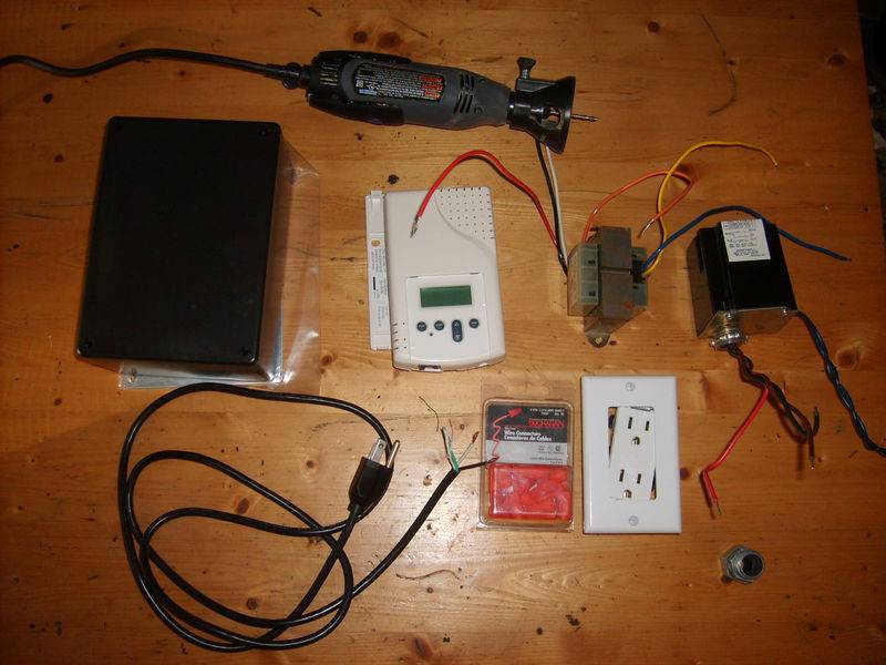


What you need...


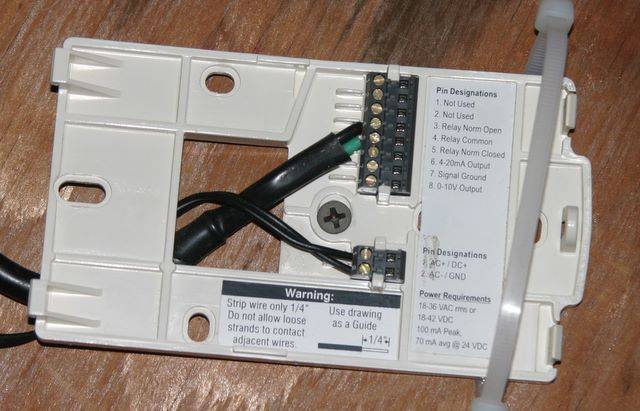
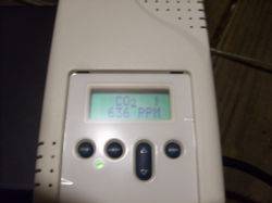
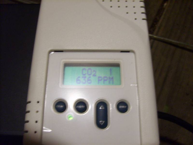
Telaire 8001 or 8002 Ventostat (I used an 8002, only difference is the 8001 doesnt have a keypad or LCD and has to be configured through a computer). This is the brains... it is what measures the CO2 and signals to the relay when give power to the outlet.

120v (Primary) to 24v (Secondary) Step-Down Transformer - provides power to the ventostat -

24v coil SPDT line voltage relay - this is what switches the outlet from having power or not....

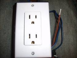
wall outlet /w faceplate - i bought a double one because it was cheaper than a single... doesnt matter as long as you know not to plug in high draw devices into it.

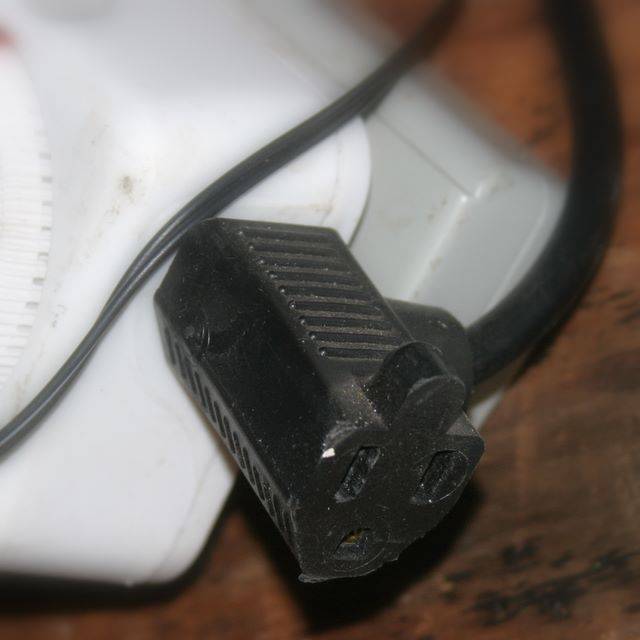
pig-tail power cord- I butchered up an old computer power cable...

plastic project box 3x5x7 - purcahsed it at radioshack... houses all the electronics
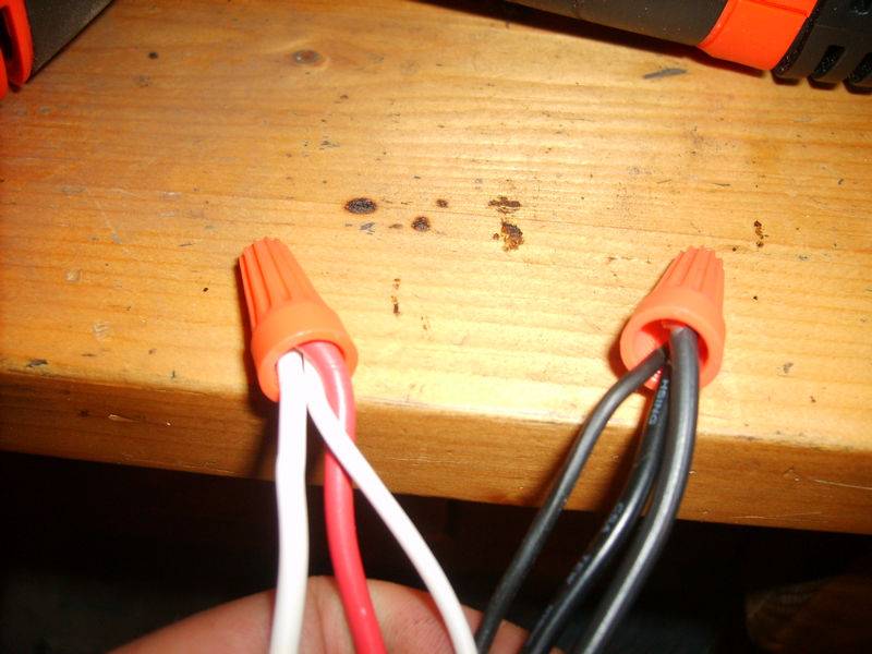
box of wirenuts

some spare wire

few random screws/bolts/nuts laying around the house...

Other tools..... dremel... drill... screwdrivers

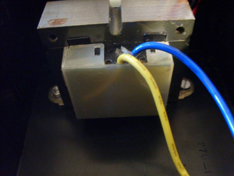
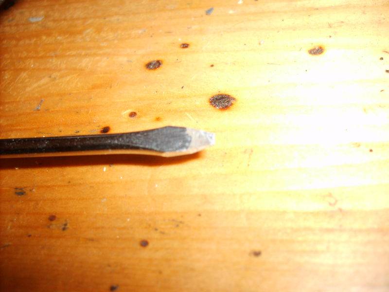
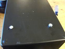
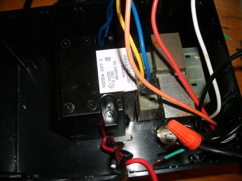
Step 1 - Plan out how you want to arrange the outlet, transformer, and relay inside the box. I started with the transformer. I mark the mounting holes with a screwdriver and then drilled them out.


Then used some small screws + nuts to secure it to the box.


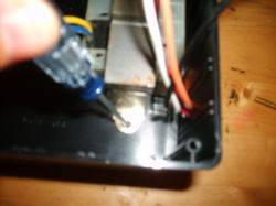
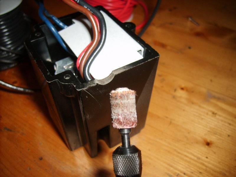
Next I removed the cover metal from my SPDT relay. Your relay may not look like this and hence other steps may be neccessary to mount it to your enclosure.


I then took a dremel with a sander bit and sanded away an indention similiar to the one already present for the blue wires...


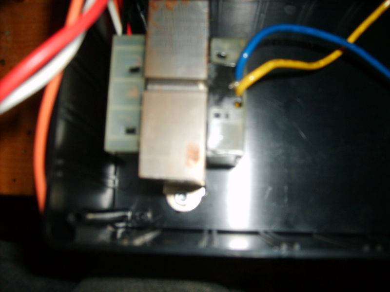
Next I placed the relay in it's position and then proceeded to mark the mounting holes with the screwdriver.


Drilled out a pilot for the mounting holes.


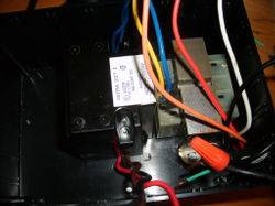
Then used the screws from the metal cover to secure the relay in place. The relay I used had a conduit connector that acted as a passive exhaut.... I drilled a few vent holes on the project box where the relay was goin to be mounted... the vent holes are not pictured.


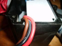
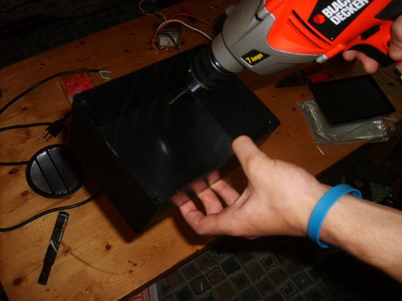
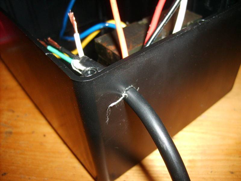
Next I drilled a hole from the incoming 120v power cord... It was slightly smaller than the cord and required a decent to tug to get the cord through.


Next....

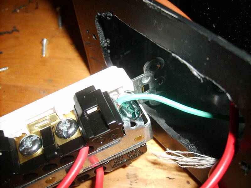
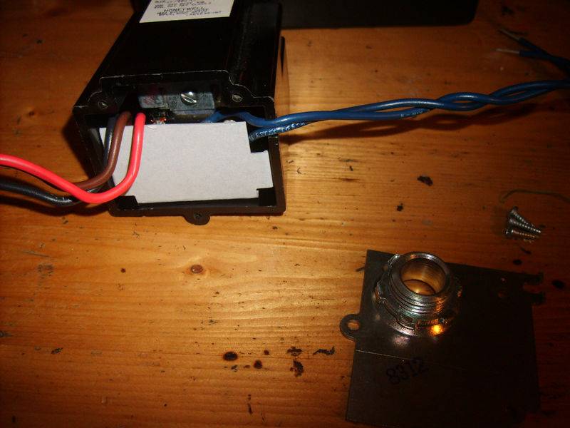
Took the dremel and used it to make a mounting hole for the outlet.


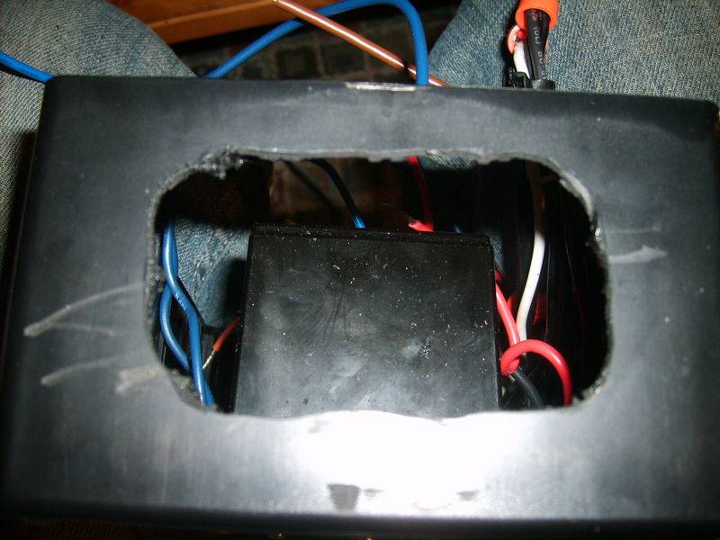
Then I proceeded to mark and drill out the pilot holes.


Here is how it looks mounted... No need to mount it yet... Still need to wire it up.
 
Last edited:

bartender187

Bakin in da Sun
Veteran
WIRING SECTION

There will be two sides to your transformer most likely... One end is called the primary and the other the secondary. If your transformer is a multi-tap transformer like mine... it will have more wires on the primary side. Below is a pic of the wires coming off the secondary end.

I still have yet to figure out which is hot and which is neutral. Below is a picture of the label on the transformer.
*POLARITY MUST BE OBSERVED IF YOU ARE POWERING THE CONTROLLER WITH AC POWER*


For this guide, I have used Blue which is labeled "24" as 24v +AC (positive) and yellow, labeled "VAC", as 24v -AC (negative).


A- Pull the 120v power cable into the box so you have enough wire to work with. Take a razor and very carefully slice down the middle and remove the outer protective layer... Make sure you dont slice the insulation on the individual wires.

B- Grab a wire nut and connect these 3 wires....

1.Hot (black) wire from the incoming 120v power cable
2.Hot (black) wire from the primary side of the 120v - 24v step-down transformer
3.Hot/Common (black) wire from the 24v coil SPDT relay

C- Grab a wire nut and connect these 3 wires....

1. Neutral (white) wire from the incoming 120v power cable
2. Neutral (white) wire from the primary side of the 120v - 24v step-down
3. Cut off a 3-5" wire lead from some spare cable, strip each end.... Connect one end to the two neutral wires, and the other to the neutral screw on the outlet (the outlets I bought were backwire outlets... yours most likely will just have a screw on the side....)


D- Take the ground from the 120v power cord and connect it to the ground on the outlet.

E- Take the Normally Closed Wire lead (brown in my case- may differ for you) and connect it to the Hot contact on the outlet. It really doesnt matter if you connect it to the Normally Closed or Normally Open wire as long as you remember to have it wired to the oposite contact on the CO2 controller... (so NC on the 24v relay.. and NO on the PPM controller or vice versa) This may sound confusing atm, but read on it should make more sense.

LOL... Umm... Yah I had the NC wire connected in this pic that is why it is red... doesnt reallly matter, but yah... later on I had switched it to the brown wire.


F- Cut (3)Three 4-5" wire leads. One end of each of these are goin to be inserted into the CO2 controller contacts. These contacts are very small, and so require very little of exposed wire. The instructions recommend stripping 1/4" of insulation off the leads. Take your 3 wires, and strip 1/4" off one end, and strip the normal required amount to fit into a wire nut on the other ends.

*POLARITY MUST BE OBSERVED IF YOU ARE POWERING THE CONTROLLER WITH AC POWER*

G- Grab a wire nut and connect two of the wires you just cut to the hot (blue, may differ for you) wire lead coming from the secondary side (output) of your 120v-24v transformer. You should have two wire leads ends with 1/4" connection not connected to anything...

H- Take the last wire lead you cut in step F and connect it to these two wires....

1. the neutral (yellow, may differ for you) wire lead coming from the secondary side (output) of your 120v-24v transformer
2. either end (doesnt matter which, but just take one) of the 24v coil wire leads (my case dark blue - may differ) from the 24vSPDT relay

I- Plan out where you want your CO2 ppm controller. The backs on these things pop off for easy? wiring... (lol i guess... imo its makes it more of a bitch) Pop off the back, mark the hole for the screws and the wires... Drill a decent size hole for the wires... big enough to pull 4 wires through... Drill pilot holes for the two mounting screws. Mount it using two screws and pull through these 4 wires....

1- the other end of the 24v coil wire from the 24vSPDT relay (darkblue)
2+3- the two hot (whatever color your spare wire is) 24volt wires leads
4-the one 24v neutral wire


-----------------------------------------------------------------------

Wiring the PPM Controller

The screws on this controller are incredibly small... I didnt have a screwdriver small enough to drive in the screws so I took my smallest flathead screwdriver (used for computers) and sanded it down to size using my dremel.


J- Take the other end of the 24v coil wire from the 24vSPDT relay (darkblue) and connect it to the contact labeled "#3 Relay Normally Open" (if you connected it to the Normally Open contact on the SPDT relay, then just connect the coil wire in this step to the Closed contact on the controller (contact #5).


K- Take the one 24v neutral wire and connect it to the contact labeled "#2 AC-"


L- Take one 24v hot wire lead and connect it to the contact labeled "#1 AC+"


M- Take the other 24v hot wire lead and connect it to the contact labeled "#4 Relay Commmon"


N - Route the wires well, and make sure no spare strands on touching any of the neighboring contacts (they are pretty close together). Stick any extra wire back into your box. Crack your box and make sure the lid will close properly, route the wires in groups into the spare gaps between the components. Screw the lid on.. and your ready to test it... With any luck your done.. : D


______________________

I hope my explainations of the wiring were clear... first time having to describe my wiring thought process... harder than i thought... heh

My reasoning behind using double relays was I was not sure if the Telaire ventostat was able to switch line voltage or just low voltage... I didnt want to risk frying the controller... takes off uneeded strain off the controller... the relay is alot cheaper to replace than the controller.

If you have any questions let me know.


__________________________________________________________
_Wiring diagram for a ethernet->serial cable,used to interface/w a comp_


spiralsmurf said:
Here's the pinout for the cable:

SERIAL (from behind the connector where the wires are):
1 2 3 4 5
6 7 8 9

Ethernet (from the top holding the jack like you were going to plug it in):

1 2 3 4 5 6 7 8

Ethernet - Serial
2-2
1-3
3-5

If my explanation of the connector orientation in unclear, let me know.

Here is the link to the software for calibrating/switching settings on the controller...

http://www.telaire.com/software/uip8000download.htm

BTW... I have yet to make one of these wires... and it does seem that my controller is out of calibration. It measures ambient outdoor CO2 at around 550-650. Should be down near 350-450.
 
Last edited:

KingRalph

Active member
awesome. glad to see ya got it workin right bartender, thanks for document the success n doin up the DIY, that's a big saver! definitely bookmarked man, nice work. be back to see it completed hehe, bravo again. peace n green thumbs :joint:
 
G

Guest

Hey bartender,

Glad to see your getting the unit together. Was wondering when you was going to get around to starting a thread. Nice to see you got everything and it's going together. You take care and another killer DIY thread. You've just got to love all the DIY members here at IC. Thanks for sharing your info and thread with us.
Take care,
BG
 
I was planning on buying a co2 controller in a month so this DIY thread could not have come at a better time.

Regards,
Sinse.
 
Last edited:

bounty29

Custom User Title
Veteran
I have no use for this, but if I ever do, I'll be back here. Awesome job explaining, good work.
 

pico

Active member
Veteran
You are the man. I might try one of these. I was thinking of wiring a photostat in to the unit to turn off co2 when lights are off.
 

bartender187

Bakin in da Sun
Veteran
^^
Yah I thought of that too... There are cheep photocells around the web. I figured I would just throw it on a timer... easier for me. Good idea : ) If you do it, please throw up a mini-diy if you get the time...
 
Last edited:

pico

Active member
Veteran
So I just snapped a few pictures of my CAP PPM-3.

Here is the inside of the unit. They made the same connections you did.


for the power they just use an external AC adapter that plugs in to the wall.


Then for turning the power on/off to the CO2 generator or tank system they use this piggy back cable.


If we could find this cable for cheap somewhere that would be nice.

I did read that all telaire 8000 series units include a spdt relay. It will switch 2 amps at 24VAC. So does that mean it would do .4 amps at 120VAC? I can't find any external SPDT relay that the CAP PPM-3 uses. Unless it is inside that piggyback cord somehow.
 

bartender187

Bakin in da Sun
Veteran
Very interesting Pico... haha that verfied my suspicions... sly mofos... slap a sticker on it and jack up the price. It seems like their is not an additional relay from the pics you posted... the solenoids and spark it takes to start up those CO2 generators/tank setups has to be quite small (under .4 amps... prob kept around .1-.2 for comfort).

Those piggy back cords can be found... I remember finding them when lookin for my parts for my E+F buckets... Ill try and see if I can dig up the link.
 
Last edited:

Stealthy

Member
This is a very interesting thread bartender! Thanks for the wonderful information. I've been using my cd-6 for years on a recycling timer cause the controller/monitors are so damn expensive. Can't wait to give this a try.
 

pico

Active member
Veteran
if you have the 8002 you can calibrate it yourself. The instructions are here. http://www.4hydroponics.com/grow_room/Mnl/capPPM3.pdf

Pretty sure you just hold CLEAR and MODE buttons for 5 seconds to get in to the options. Then push MODE 9 times to get to AMBIENT and change it to around 450 or so. It is all in the instructions above but if I recall that is the sequence.


GDW- Thanks for those links. I am going to call them this week to see if that is what I am looking for. I think these piggyback cables might just always supply power to the piggy back. The piggyback cable on the ppm-3 somehow switches the piggyback on/off.
 
G

Guest

Good luck pico.

If i come across a site with some prices. I'll be sure to post it. I know the type your looking for. You want power all the time on both ends. Good luck with the project everyone.
Take care,
BG
 

bartender187

Bakin in da Sun
Veteran
Pico- From the pics you posted this is what I gather... The PPM3 receives power from a external AC/DC adapter... then there is a seperate piggy back cord that controls the CO2 equipment... It plugs into a timer or wall outlet... its a non-standard piggy back cord, that should have two sets of 3-wire leads (one for the male plug, the other for the female plug... You wire neutral to neutral... male plug hot to the relay common... female plug hot to relay normally closed... ground to ground)... thanks for the info on how to calibrate the meter... I called up telaire.. they wanted $65 and a two week turnaround to do it.
 

pico

Active member
Veteran
GDW- Actually I don't want the piggy back on all the time. I want to switch it with the ppm-3.

187- There are only 2 wires coming from the piggy back in to the ppm-3. I think what might be happening inside there is this. The common wire from the male end of the piggy back goes to the ppm-3 pin #4(relay common) and then the common wire from the female end of the piggyback cable is connected to the ppm-3 @ pin #3(relay normally open).

The hot and ground wires would just be directly linked between the male and female parts of the piggy back cable. The ppm-3 would switch the female end of the piggy back on and off by opening and closing the common circuit.

Is this thinking correct?

 
Top