What's new
  • Happy Birthday ICMag! Been 20 years since Gypsy Nirvana created the forum! We are celebrating with a 4/20 Giveaway and by launching a new Patreon tier called "420club". You can read more here.
  • Important notice: ICMag's T.O.U. has been updated. Please review it here. For your convenience, it is also available in the main forum menu, under 'Quick Links"!

DIY Ebb & Flo Bucket Controller and System

G

Guest

DIY Controller and System

I just wanted to do a step by step thread for everyone that was thinking about building one of these systems or just the controller. I did not invent this system. Just like Kryptonite, i'm just trying to save some money and build a cool system. Anyone has any questions. Feel free to ask away. I'm going to try to make this as easy as possible for everyone to understand. First is going to be a part's list.

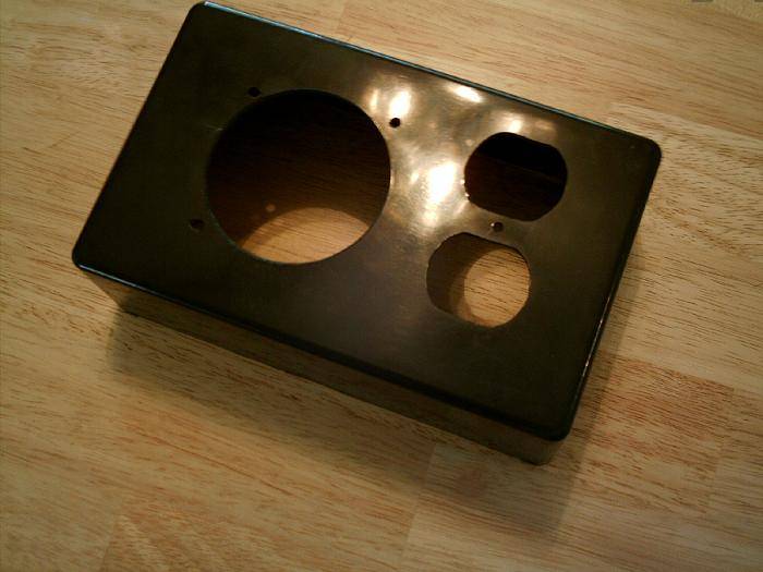
Handy Boxes with Aluminum Panel
PB160 4-1/8 x 2-1/8 x 1-1/2

http://www.oselectronics.com/ose_p83.htm
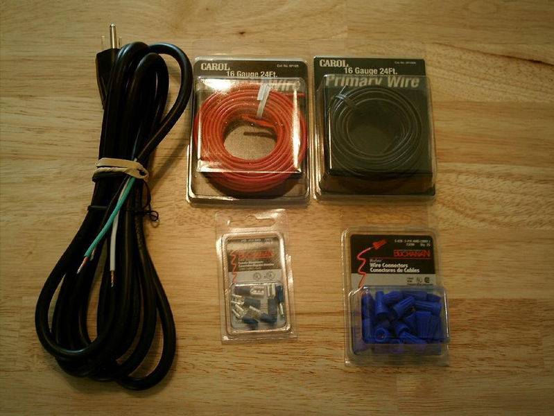
Line Cords
3 Wire Line Cords
Type SJT Cord Set. Standard NEMA 5-15P
Power plug.
UL Approved.
ACL169 16 9'

http://www.oselectronics.com/ose_p116.htm
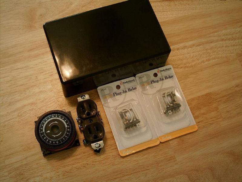
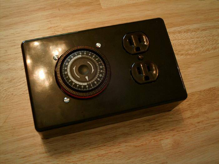
Part Number: TA4079
Description: Time Clock, 24Hr, 120V, SPDT 5 Term


http://www.poolandspa.com/catalog/product004500000385.cfm

125VAC/10A DPDT Plug-In Relay

www.radioshack.com

AC 15A 125 volt outlet

Found at any hardware store. Lowes/Home Depot

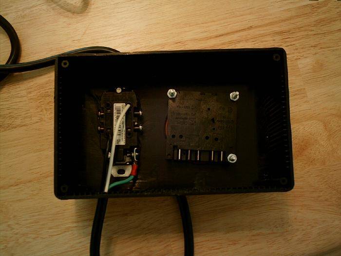
2 rolls of 16 guage wire. Red and Black. Found at Lowes/Home Depot

#16-#14 300volt Female Disconnects Found at Lowes/Home Depot
#20-#16 300volt Wire Connectores or Wire Nuts. Found at Lowes/Home Depot
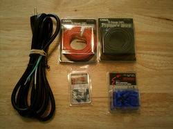


Last edited:
G

Guest

Ok, just drilled out the hole for the timer. First you want to drill a pilot hole for the whole saw drill your going to use to drill out the timer hole. You want to drill a pilot hole, so the whole saw doesn't want to walk on you. This will allow you to make sure the hole is centered.

Tool's Needed

One Drill
One 2.5" Whole Saw
One small drill bit for drilling pilot hole


G

Guest

Morning all, just got done cutting out the holes for the power outlets and mounitng everything into the box. Let's get to it and get everying together.

Tool's Needed

Dremel type tool
Cutting bit for dremel tool
Drill
1/16 drill bit
9/64 drill bit

Hardware Needed

One pack of #6-32 x 1 1/2" Machine scews with nuts
AC outlet
Plastic Box
Timer
Paint Marker

Ok, what i did to cut out the power outlets holes. Was used one of the outlet cover in my house. I turn one around and used a paint marker and traced a outline, so it would be easy to cut out the hole's. All i did was take my dremel power tool and cut away at the painted part. Here are some pictures of the steps.


Last edited:

blackfin

Member
^^^^ ditto... maybe this is my ticket to hydro, since i wouldn't need a res under a table... thanks bro
 
G

Guest

Thanks bartender187, glad to see you found your way over. This unit should be in use by Dec. Just getting everything ready for my up coming return. Thanks for stopping by.
Take care

Thanks blackfin, glad to see you also. This unit should do very well. Your right about the rez. You can place the rez any place you like. Once you get these units setup. They are pretty much bullet proof. Thanks for stopping by also.
Take care,
BG

For all the readers. I'm just following this thread Krypto's did and thought i would do a thread myself with some other changes. Krypto was the one that really did all the work. I'm just following his foot steps and doing alittle changes myself.
Thank you Krypto
 
G

Guest

Afternoon everyone and thanks for all the kind words and support. Here's alittle update and i'll be doing alot more updating this night and over the weekend. Thanks again for stopping by.
Take care

Well, I ran the power cord to the outlet. First i drilled a hole at the bottom of the box. What i did is found a drill bit about the same size as the power cord and then drilled the hole. Once that was done. I ran the cord and attached the ground to the ground screw. Once that was done. I attached the Hot wire and then the Neutral. I'm not going to get into wiring, because i don't want someone to get hurt or even worse. Black is "HOT" and "White" is Neutral and green is ground. You can find sources on the internet about wiring. Here is a picture of how i wired my outlet. I'm not good with wiring and just found some info on the internet and did what they said. Once i got the outlet wired. I got a light and tested the outlet. Both outlet plugs worked fine. Here's a picture of the back of the box. Next update will be the bucket controller.

 
Last edited:

Budweiser13

Active member
Thanks for taking the time to do a step by step. I for one really appreciate all the people on this site that put the time into this stuff it makes it so much more easy to learn. It is like going to cannabis college..... :woohoo:
 
G

Guest

Thanks Budweiser. I'll try and do my best at making it as easy as possible.
Take care.

Afternoon all. I'm going to update more later on tonight. Going to showing mounting the box to the bucket.

Tools Needed

One drill
One drill bit size of screws being used or a tad bigger.
screw driver


Hardware Needed

One five gallon bucket
One Time box
Screw's and Nuts for mounting

Ok, first you need to gather up all the tools needed and harware. Once you got them. What i did was removed the metal plate from the back of the timer box. With the box i'm using. It's a metal plate and will need to be drilled to mount to bucket itself. What i did first was measure across the plate. Was right at 7 inches, so i divided the 7 inches and drilled the first hole at 3.5". Once i got the first hole drilled. I drilled two more holes. I drilled one on each side to help support the timer box better. Your going to have to keep them close. Since the bend of the curve in the bucket. Not hard at all. During the mounting process. You want to use a level to make sure you timer box is level. You don't want your box to be unlevel and looking like shit. All i could find for a level around the house was this type, but you can use just about any level that is small enough, or you could just eye it. Here's some pictures of the process. I'll update later on tonight the mounting of the float switches. I ran into some trouble with the switch, but i'll go over that later on.
Thanks


mrwags

********* Female Seeds
ICMag Donor
Veteran
Well if the book turns out something like this I do believe we might have a bestseller on our hands. Great job as always.


Mr.Wags
 
G

Guest

Thanks everyone, just here trying to help out. Plus, i'm bored since i can't grow and I just wanted to get things lined up till i can grow again. Nice to see everyone visiting and their support.
Thanks


Drilling Float Switch Holes

Tools Needed

Drill
7/16 Drill Bit
1/4-18 NPT Tap
Tape or Ruler
Marker or Felt Pen

Hardware & Supply

1 5 gal Bucket
4 Float Switches
4 90 Degree elbows threaded one sided
Epoxy

Once you get everything together. You'll need to take your measurments and make your marks that needs to be drilled. If you folow the pictures. You will see the measurement for the holes. The first holes i drilled was the bottom float switches that drain the controller. The second set of holes are for the fill max switches.

Measurements

First hole is 4" inches from the bottom
Second Hole is 4.5" or 4 1/2" inches from bottom of bucket.
You want to make sure you center them and have a 2" inch space between them.

 
G

Guest

Mounting Float Switches

Ok, after you've drilled the holes. Your going to have to screw in the elbows. You want to screw the elbows from the inside of the buckets. Once you have drilled the holes. You want to run the tap through the holes and thread them. Once you have the thread through the holes. You want to mix up some epoxy. Once you got some epoxy mixed up. You want to apply it to the threads of the elbows and the threaded holes. Once that is done, your going to screw in the elbows one at a time. Once the elbows are all in and installed. Your going to need to feed the wires through the elbow and screw in the switched, but before you do that. You want to apply some epoxy to the inside of the threads to seal the elbows up, so they don't leak. Ok, now you've applied the epoxy. Now, screw in the float switched and let the epoxt dry.

Float Switch found here.


Last edited:

Babbabud

Bodhisattva of the Earth
ICMag Donor
Veteran
Great thread and a great setup for growing very fast . Thanks for the time and effort you put into this friend its a great tutorial. :)
 
G

Guest

Thanks Babbabud, just trying to keep busy.

Misc

Tools Needed

Drill
7/8" or 22mm Hole Saw bit
Small Pilot Drill bit

Hardware Needed

3, 3/4" barbed straight coupling
3, 3/4" Rubber Grommet
Epoxy

Ok, i missed this step and thought i would go back. I want to try to hit every step of construction. Here you are going to install the bottom fill and drain fitting at the bottom of the controller unit. These are the fittings that fill and drain all the grow sites. I went with 3/4" because i wanted better flow and no chance of cloging in tubing. This step is pretty easy. Just figure out where you want the fittings. I went off to the side like most. This keeps the lines out of the way of the timer box. Mark the spot you want the first fitting. I marked the middle fitting first to center everything. Then i drilled the outter ones. There was not special measurements. Just got the fittings as low as i could and spaced them about 3/4-1" apart.


Top