A 1 minute on/4 minute off cycle timer you can make yourself for about $4.
Step-by-step format, with basic soldering skills anyone can build a working timer. For the more experienced it`ll be a walk in the park :wink:
I haven`t had a timer fail but they are so cheap its worth building a couple so you always have a backup available. The relay or the IC are the most likely things to fail after extended use (its no different for commercial timers). For that reason an IC socket provides for plug and play chip replacement and the relay is connected via flying leads so it can be changed out swiftly too if need be.
The components are fairly easy to find at electronic shops or online. The component list is ordered to match the Circuit Layout Diagram attached.
I`ve no clue how to post pics directly into a thread so it doesn`t flow too well. Anyway, here`s what you need:
A piece of veroboard/stripboard at least 11 copper tracks deep and 25 holes wide (approx 2.5" x 1.25")
D1,D2: 1N4148 Signal Diodes
R1: 1K ohm 1/4w carbon film resistor
IC1: NE555 timer
8-Pin IC Socket
C3: 100uF 16v Radial Electrolytic Capacitor (uF= MicroFarad)
C1: 100nF Multilayer Ceramic Capacitor (nF= NanoFarad)
C2: 100uF 16v Radial Electrolytic Capacitor
D3: 1N4007 Rectifier Diode
R5: 470K ohm 1/4w carbon film resistor
R2: 1K ohm 1/4w carbon film resistor
R3: 3M3 ohm 1/4w carbon film resistor
R4: 220K ohm 1/4w carbon film resistor
Relay: 10A/20A 120 or 240vac DPDT with a 12v dc coil
The choice of relay is up to you, the important thing is to make sure the contacts are rated for your mains voltage, 120 ac or 240v ac. It must have a 12vdc coil with a coil resistance not less than 60 ohms but most are well over that so its not a big problem.
You`ll also need some solid core hookup wire for the "wire links", a box or two to put it in and some electrical connector blocks.
The timer requires a small 12v dc regulated power supply, the plug-in multi-voltage type power adapters are ok (1.5/3/4.5/6/9/12v at 300mA).
The total cost for the components including the relay but excluding the box,power supply will be around $4 or less.
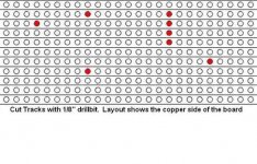
The first job is to cut the copper tracks on the veroboard/stripboard in several places using a 1/8" (3mm) HSS drill bit or a track cutting tool if you have one.
Again, apologies for not being able to post the pics directly in the thread..i`ll learn how one day, the one you need here is the "Track Cutting Details" pic.
Gently rotate the drill bit or track cutter to remove the copper and create a gap in the track. Don`t drill a hole right through the board :wink:
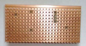
You can verify the track cuts are open-circuit by using the continuity function on a multi-meter if you have one.
The "Track Cutting Done" pic shows what it should look like when you`re done.
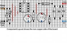
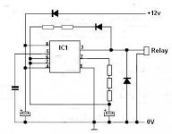
The "Circuit Layout Diagram" pic shows you where everything goes. The X`s mark the track cuts on the underside of the board which will help you figure where the various components fit. The vertical red lines are the wire links.
Be very careful to count the number of holes each component covers..you dont want to get something in the wrong hole :wink:
Time to put it together,
Fit the 8-pin IC socket first. Place the IC socket with the small U-shaped notch at one end facing towards the top of the board in the correct position in relation to the track cuts (see Circuit Layout Diagram).
Bend the socket pins over towards the holes you cut in the track to hold the socket and then solder it into place.
Make sure you don`t bridge any solder across the pins
Next, fit the 5 Wire Links using the solid hookup wire as shown on the Circuit Layout Diagram. These are marked as plain vertical red lines.
Fit D1 (IN4148) noting the direction of the black band.
Fit D2 (1N4148) noting the direction of the black band and R1 (1K resistor) Note D2 and R1 legs share a single hole position.
Fit D3 (1N4007) noting the direction of the white band which is marked as a black band on the layout. (There is a track cut (x) behind this diode to help with its location)
Fit C1 (100nF capacitor) it`ll be a tiny blue thing, you will have to bend the legs gently to get it to fit across the 5 holes. Then fit R2 (1K),R3 (3M3),R4 (220K) and R5 (470K).
Fit C2 (100uF radial capacitor) making sure the - minus sign on the side of the capacitor aligns with the bottom hole on the layout diagram. Be aware this capacitor covers 4 holes.
Now fit C3 (100uF radial capacitor) again making sure the - minus sign on the side of the capacitor aligns with the bottom hole on the layout diagram. This capacitor covers just 3 holes.
Solder the two wires to the left side of the board near D1 and terminate them in an electrical connector block, this connects via flyleads to the 12v dc relay coil.
Solder the red and blue wires (or your own colour code) to the right side of the board as shown in the layout diagram for +12v and 0v, these connect to the regulated 12vdc power supply.
Plug the 555 chip into the IC socket making sure the U-shaped notch on the chip is facing upwards to match the socket
You may have to squeeze the pins gently inwards to get it into the socket.
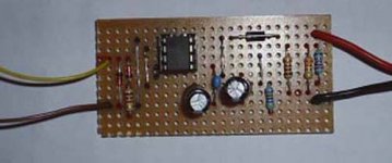
You should now have something that looks like the "1min_4min cycle timer done" pic. Power it up to test it works and then put it in a box.
Wiring up the mains side of the relay will depend on where you live (EU,US etc) but shouldn`t pose any problems. Make sure you mount it well away from the timer circuit board, or ideally put it in a seperate box with the mains supply going to the relay and a mains outlet from the relay going to the pump. The DPDT relay will switch both the live and neutral so you`ll just need to common the earths inside the box.
Have fun, Peace
Step-by-step format, with basic soldering skills anyone can build a working timer. For the more experienced it`ll be a walk in the park :wink:
I haven`t had a timer fail but they are so cheap its worth building a couple so you always have a backup available. The relay or the IC are the most likely things to fail after extended use (its no different for commercial timers). For that reason an IC socket provides for plug and play chip replacement and the relay is connected via flying leads so it can be changed out swiftly too if need be.
The components are fairly easy to find at electronic shops or online. The component list is ordered to match the Circuit Layout Diagram attached.
I`ve no clue how to post pics directly into a thread so it doesn`t flow too well. Anyway, here`s what you need:
A piece of veroboard/stripboard at least 11 copper tracks deep and 25 holes wide (approx 2.5" x 1.25")
D1,D2: 1N4148 Signal Diodes
R1: 1K ohm 1/4w carbon film resistor
IC1: NE555 timer
8-Pin IC Socket
C3: 100uF 16v Radial Electrolytic Capacitor (uF= MicroFarad)
C1: 100nF Multilayer Ceramic Capacitor (nF= NanoFarad)
C2: 100uF 16v Radial Electrolytic Capacitor
D3: 1N4007 Rectifier Diode
R5: 470K ohm 1/4w carbon film resistor
R2: 1K ohm 1/4w carbon film resistor
R3: 3M3 ohm 1/4w carbon film resistor
R4: 220K ohm 1/4w carbon film resistor
Relay: 10A/20A 120 or 240vac DPDT with a 12v dc coil
The choice of relay is up to you, the important thing is to make sure the contacts are rated for your mains voltage, 120 ac or 240v ac. It must have a 12vdc coil with a coil resistance not less than 60 ohms but most are well over that so its not a big problem.
You`ll also need some solid core hookup wire for the "wire links", a box or two to put it in and some electrical connector blocks.
The timer requires a small 12v dc regulated power supply, the plug-in multi-voltage type power adapters are ok (1.5/3/4.5/6/9/12v at 300mA).
The total cost for the components including the relay but excluding the box,power supply will be around $4 or less.
The first job is to cut the copper tracks on the veroboard/stripboard in several places using a 1/8" (3mm) HSS drill bit or a track cutting tool if you have one.
Again, apologies for not being able to post the pics directly in the thread..i`ll learn how one day, the one you need here is the "Track Cutting Details" pic.
Gently rotate the drill bit or track cutter to remove the copper and create a gap in the track. Don`t drill a hole right through the board :wink:
You can verify the track cuts are open-circuit by using the continuity function on a multi-meter if you have one.
The "Track Cutting Done" pic shows what it should look like when you`re done.
The "Circuit Layout Diagram" pic shows you where everything goes. The X`s mark the track cuts on the underside of the board which will help you figure where the various components fit. The vertical red lines are the wire links.
Be very careful to count the number of holes each component covers..you dont want to get something in the wrong hole :wink:
Time to put it together,
Fit the 8-pin IC socket first. Place the IC socket with the small U-shaped notch at one end facing towards the top of the board in the correct position in relation to the track cuts (see Circuit Layout Diagram).
Bend the socket pins over towards the holes you cut in the track to hold the socket and then solder it into place.
Make sure you don`t bridge any solder across the pins
Next, fit the 5 Wire Links using the solid hookup wire as shown on the Circuit Layout Diagram. These are marked as plain vertical red lines.
Fit D1 (IN4148) noting the direction of the black band.
Fit D2 (1N4148) noting the direction of the black band and R1 (1K resistor) Note D2 and R1 legs share a single hole position.
Fit D3 (1N4007) noting the direction of the white band which is marked as a black band on the layout. (There is a track cut (x) behind this diode to help with its location)
Fit C1 (100nF capacitor) it`ll be a tiny blue thing, you will have to bend the legs gently to get it to fit across the 5 holes. Then fit R2 (1K),R3 (3M3),R4 (220K) and R5 (470K).
Fit C2 (100uF radial capacitor) making sure the - minus sign on the side of the capacitor aligns with the bottom hole on the layout diagram. Be aware this capacitor covers 4 holes.
Now fit C3 (100uF radial capacitor) again making sure the - minus sign on the side of the capacitor aligns with the bottom hole on the layout diagram. This capacitor covers just 3 holes.
Solder the two wires to the left side of the board near D1 and terminate them in an electrical connector block, this connects via flyleads to the 12v dc relay coil.
Solder the red and blue wires (or your own colour code) to the right side of the board as shown in the layout diagram for +12v and 0v, these connect to the regulated 12vdc power supply.
Plug the 555 chip into the IC socket making sure the U-shaped notch on the chip is facing upwards to match the socket
You may have to squeeze the pins gently inwards to get it into the socket.
You should now have something that looks like the "1min_4min cycle timer done" pic. Power it up to test it works and then put it in a box.
Wiring up the mains side of the relay will depend on where you live (EU,US etc) but shouldn`t pose any problems. Make sure you mount it well away from the timer circuit board, or ideally put it in a seperate box with the mains supply going to the relay and a mains outlet from the relay going to the pump. The DPDT relay will switch both the live and neutral so you`ll just need to common the earths inside the box.
Have fun, Peace